Dr. Rohit Sachdeva discusses how the unique features of suresmile’s IDB can lead to predictable bonding and treatment outcomes
Introduction
In its goal to better patient care, the profession of orthodontics is cautiously transforming conventional care delivery from an analog, reactive, and standardized approach to a digital, proactive, and customized approach. This digital care platform is enabled by technologies such as 3D imaging, computer-aided design software, and robotic and 3D printing. Recently, suresmile® has expanded its technology repertoire from prescriptive, customized archwires for finishing — commonly used in the latter half of treatment — to include indirect bonding (IDB) trays. IDB trays facilitate a more accurate, precise, and efficient placement of brackets at the start of treatment.1
In addition to the proper use of suresmile technology, I must emphasize that a robust plan and the appropriate management of the patient are the driving forces for any successful treatment outcome. This is the central tenet of my philosophy and practice of biodigital orthodontics and is discussed in my previous articles.2-5
 This article will discuss the design principles for and chairside technique of bonding with the suresmile IDB tray, explaining how the unique design features of the suresmile design software and IDB tray allow for more predictable bonding and treatment outcomes.
Designing the suresmile IDB tray
The suresmile IDB tray is designed on the virtual dental working model, also known as the virtual diagnostic model. (Note from author: I prefer the phrase “virtual dental working model” as it better describes the use case of the model. And when I use it for diagnostics, I call it the virtual diagnostic model.) The dentition may be imaged in two ways in order to create the virtual dental working model.
Direct in vivo optical scanning
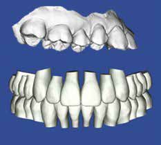
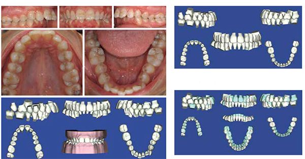
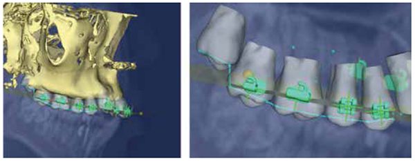
Direct in vivo optical scanning is the optimal approach to obtain an accurate digital representation of the malocclusion6-7 (Figure 1); suresmile recommends this method. A number of suresmile-certified, light-based scanners may be used for image capture (Table 1). Prior to scanning the patient, it is best to smooth jagged tooth edges or surface aberrations to allow for better fitting trays.
Indirect in vitro optical scanning
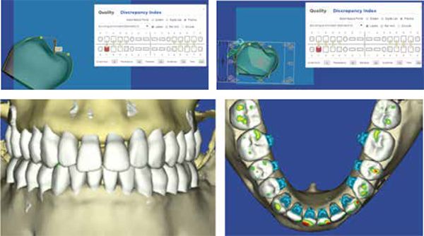
Indirect in vitro optical scanning involves scanning the plaster model of the malocclusion; any of the suresmile-certified, light-based scanners may be used for imaging. This approach to image capture is not recommended by suresmile due to the loss of accuracy that occurs when taking impressions and pouring the model in plaster. If the clinician opts for indirect in vitro optical scanning, he/she should take a PVS impression and pour the model in hard stone (Figure 2). As a word of caution, the processing of such models faces a high-rejection rate from the suresmile laboratory, delaying the delivery of the tray.

Types of suresmile IDB trays
The suresmile laboratory processes the 3D virtual dental working model within 2 business days of receiving the raw scan data from the practice. I classify the IDB trays into three types — namely types 1, 2, and 3.
Type 1 IDB tray
Type 1 is the most common tray used. The design of the type 1 tray is based upon an intrarch setup and follows the straight archwire paradigm.8 Each arch is treated independently, and the only variables considered in this setup are crown morphology, relative spatial position of the teeth, archform, and bracket prescription. The type 1 arch is indicated in patients who require first- and second-order tooth corrections with a minimal need for third-order movements to coordinate the upper and lower dental arches (Figure 2). Local third-order corrections are managed by choosing the appropriate bracket prescription from the bracket library or by preferentially placing the brackets (i.e., inverting the brackets).
The design sequence for the tray replicates the clinical procedures a clinician follows when he/she directly bonds a patient; this process consists of four steps, which are described below in the following stepwise guide.
Step 1: virtual pre-bonding phase (Figures 3 and 4)
- Bracket system selection
- The clinician selects the bracket system of his/her choice from the electronic bracket library. (The library has over 30,000 bracket systems or types to choose from.) If the bracket type is unavailable, suresmile will scan the type into the library upon receiving a request from the doctor or manufacturer.
- Bracket height selection
- Bracket heights may be customized to suit individual preferences or may be based on measures guided by the doctor’s treatment philosophy.
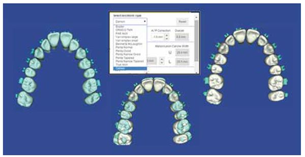
- Archform selection
- The treatment archform is selected from the menu. The necessary parameters need to be only input once and are stored in the system under the doctor’s preferences. At any point in time, this list may be modified to include different bracket systems, heights, etc.
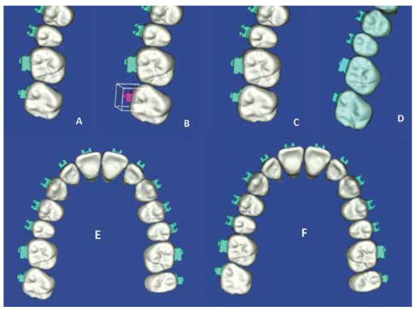
Step 2: virtual initial bonding phase (Figure 3)
- Automatic bracket placement
- The software automatically populates the dentition with the selected brackets at the selected heights.
- Bracket position evaluation and correction
- Bracket positions are quickly evaluated. A bracket that appears misplaced may be readily corrected using the software’s navigational tools.
Step 3: virtual target setup (Figure 5)
- Automatic virtual target setup
- Based upon the selected bracket heights and archform, the software automatically generates a 3D virtual intrarch target setup.
- Virtual target setup evaluation
- The target setup is evaluated for any incorrect tooth positions. Again, corrections are easily performed using the navigational tools, and radiographs may be used to estimate root position and make appropriate corrections to the setup. Bracket position corrections in the virtual target setup are automatically synchronized with bracket position adjustments on the working model.
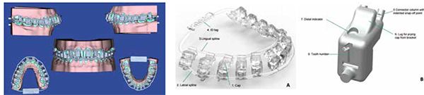
Step 4: virtual IDB tray design and order (Figure 6)
- Automatic IDB tray design and order
- The IDB tray is designed automatically. If the clinician needs sectional trays, appropriate segments are selected in the menu, and the software automatically generates the trays for sectional use. The trays are ordered following this step.
The entire process of designing the type 1 IDB tray typically takes less than 5 minutes of operator time. The IDB tray is produced using additive 3D printing technology and is fabricated from MED610, a biocompatible polymer manufactured by Stratasys® (Stratasys, Eden Prairie, Minnesota). The tray is shipped within 5 business days of receiving the virtual IDB prescription from the practice.
Clinical technique for bonding with the suresmile IDB tray
The following section summarizes the technique for bonding with the suresmile IDB tray (Figures 6A and 6B). Emphasis is placed on the procedures specific to the use of the suresmile IDB tray.
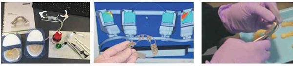
Step 1: IDB tray check and preparation (Figures 8A and 8B)
- Tray integrity and design is first verified against the virtual tray image on the computer.
- Since the tray is not produced in a sterile environment, it should always be wiped down with isopropyl alcohol prior to use. Acetone reacts with the tray material and will damage the tray; therefore, acetone should never come into contact with the tray.
- The patient ID tag should be snipped off with scissors prior to use (Figure 9).
- The tray material is biocompatible and is certified to be in contact with the oral mucosa for up to 24 hours.

Step 2: loading brackets in the trays and application of the adhesive (Figures 10A-10D and 11A-11C)
- The prescribed brackets should be loaded. Prior to loading self-ligating brackets, the doctor should make sure that the bracket doors are firmly shut.
- The bracket is seated using gentle finger pressure aided with a scalar. Molar brackets are best seated by pushing them against the receptacle wall in a downward direction.
- Each bracket base is wiped clean with alcohol and allowed to dry.
- The adhesive is applied in clean strokes in a mesial-to-distal direction (e.g., Transbond™ XT Light, 3M Unitek, Monrovia, California). Vertically guided strokes may dislodge the bracket from its receptacle.
- A primer or sealant (e.g., Opal® Seal™, Opal® Orthodontics, South Jordan, Utah) is applied to an applicator and is used to gently press the adhesive into the pad mesh.
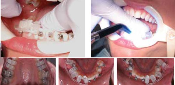
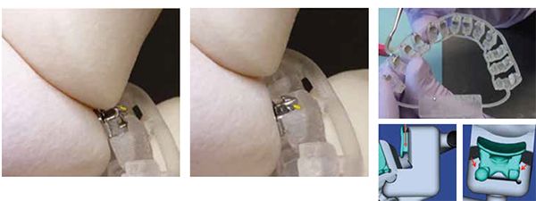
Step 3: tooth preparation and bonding (Figures 12A and 12B)
- The techniques of standard Isolation with cheek retractors, etching, and priming are used to prepare the teeth for bonding.8-12
- The tray is seated by applying firm pressure on the occlusal surface and firmly pushing against the labial and buccal surfaces of the teeth.
- It is preferable to use a curing light with a small tip to cure the adhesive (e.g., American Orthodontics’ Blue Ray 3 microflash LED curing light (American Orthodontics, Sheboygan, Wisconsin). The light should travel over the buccal and labial surfaces of the teeth as well as the gingival margins. It is best to exceed the light manufacturer’s recommendations for curing time.
Step 4: IDB tray removal (Figure 13)
- Once cured, the lingual spline is snipped away from the tray by cutting the supporting connector arm for each bracket receptacle with ligature cutters.
- The lug on the occlusal surface of the bracket receptacle is used as a lever to gently lift and peel the receptacle away from the tooth.
- The tray or tray segment is then pulled away occlusally.
Step 5: bonding check
- The bonded brackets’ positions are checked against their positions on the virtual dental working model.
- A discussion of clinical indications and design characteristics of the types 2 and 3 IDB trays follow.
Type 2 IDB tray
The design of the type 2 IDB tray is based upon a 3D interarch virtual target setup of the dentition. The type 2 arch is indicated in patients (a) whose treatment will involve a significant amount of interarch corrections through facial orthopedics or surgery, (b) who need a significant amount of interarch form coordination through precise archwidth and torque control, (c) who have skewed and canted upper and lower arches and present with substantial variations in tooth morphology, (d) in whom dento-alveolar compensations need to be maintained, and (e) who require lingual orthodontic treatment (Figures 14-16).
Two factors need to be considered in the design and use of type 2 IDB trays. First, type 2 trays are best designed by the suresmile laboratory rather than by the orthodontic practice since the creation of the virtual setup requires a substantial time commitment from the orthodontist and care team. Second, many variables impact final tooth position, such as variation in tooth morphology, the force-system dissonance between the ideal bracket height and desired torque and bracket archwire play,13-19 etc. Unfortunately, such issues cannot be solely managed by IDB or the use of customized bracket prescriptions. To overcome these limitations, the clinician needs to pair IDB with the use of robotically bent, 3D precision archwires to achieve reliable treatment outcomes (Figures 17-20).


The suresmile software provides the clinician the tools to design both the IDB tray and customized archwires in tandem (if he/she so chooses). However, as previously mentioned, the creation of the virtual target setup is best managed by the suresmile laboratory in concert with the clinician’s input. Design considerations for the virtual target setup and suresmile robotically bent prescriptive archwires have been described in previous articles.2-5 The setup services and the archwire production provided by suresmile come at an extra cost to the doctor and add a minimum of 10 business days to the delivery of the type 2 IDB tray.
Type 3 IDB tray
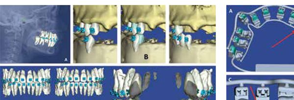
The type 3 IDB tray is indicated in “high-risk” patients. This patient is commonly an adult female whose dentition is severely periodontally compromised and who seeks an uncompromised treatment result. Successful treatment for such a patient requires a comprehensive care plan developed from a thorough assessment of the 3D crown and root positions with respect to (1) their location in the alveolar bone and (2) their relationship to the soft tissues (lips, gingiva). In addition, the therapeutic management of such a patient demands 3D control of tooth movement through the entire care cycle.
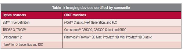
The 3D virtual dentofacial working model representing the dentofacial complex is constructed from an amalgamation of different images. These images include a 3D CBCT image of the dentofacial complex, an optical scan of the dentition, and a 2D frontal photograph of the patient. Note: Only
suresmile-certified CBCT machines and optical scanners may be used for imaging; these are shown in Figure 21.
Optical scans are necessary because the models processed from CBCT scans do not accurately represent the incisal edges of the anterior teeth, making it difficult to print well-fitting IDB trays. To overcome this limitation, a supplemental in vivo scan of the patient’s dentition needs to be taken with a suresmile-certified optical scanner. This scan is then fused with the CBCT image to create a model that accurately represents the crown and root morphology and position with respect to the alveolar bone.
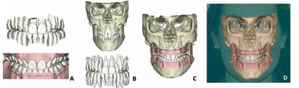
In addition, a 2D planar frontal facial image (if provided) is superimposed on this 3D dental-skeletal model to create a virtual integrated working model. This virtual dentofacial working model is used to design an interarch “3D biologically driven” setup (Figures 22 and 23). As a clinician might expect, it is impossible to achieve “3D biologically driven” optimal tooth positions solely based upon the notion of idealized bracket positions and/or bracket prescriptions. Predictable tooth movement necessitates the use of the type 3 IDB tray complemented with robotically bent 3D prescription archwires and auxiliary appliances that generate consistent force systems (Figure 24). Again, it should be recognized that these additional services are cost additive and increase the delivery time of the tray.

The clinical technique for bonding with types 2 and 3 suresmile IDB trays is similar to the Type 1, as described earlier.
There are many features of suresmile technology that provide the clinician the ability to design IDB trays that aid in accurate, precise, and efficient bonding. A discussion of these features follow: (1) software capabilities that allow the doctor to make better judgments on bracket position and (2) the physical attributes delivered by the suresmile IDB tray (i.e., how the suresmile IDB tray facilitates targeted indirect bonding in an efficient and effective manner in the clinical setting).
3D virtual dental and dentofacial working models
3D model accuracy is an important consideration in the accurate design of an IDB tray. suresmile 3D optical-scanned models have been shown to be the most accurate in the industry.20
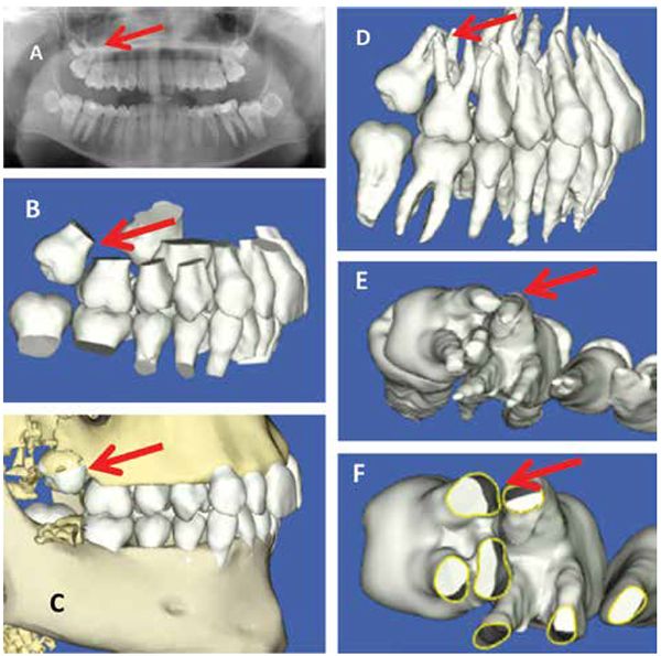
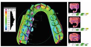
The 3D model overcomes the limitations of and errors associated with the 2D planar view. The 3D model provides the doctor with unrestricted multiplanar views of the dentition simultaneously. These views allow for a better understanding of the impact of tooth morphology on bracket position — and subsequently tooth displacement (Figure 25). In addition, multiplanar views can be effectively used to view the conformance of the bracket pad to the tooth surface (Figure 26). This impacts adhesive thickness, which impacts bond strength and, as a result, bracket failure.21 With such information, the doctor can place the brackets more strategically to avoid bracket failure.


Furthermore, the virtual dentofacial working model gives the orthodontist a fresh pair of eyes to better appreciate the complex interrelationships that exist among the various dental, skeletal, and soft tissue components of the dentofacial complex. This perspective allows the doctor to consider a “biologically driven” approach to bracket placement (Figures 27 and 28).2-5 The virtual dentofacial working model enhances the doctor’s ability to design bracket placement on the basis of esthetic considerations (Figure 22).22-23
Since the virtual dental and dentofacial working models reside in the cloud, the doctor and his/her care team can remotely access the model and work synchronously or asynchronously to design the IDB tray. A virtual model is in no danger of destruction, which is a concern with physical models.
Universal electronic bracket library
As previously stated, the suresmile electronic bracket library houses over 30,000 bracket types or sets. This library allows the orthodontist various options in terms of selecting the appropriate bracket prescription for the patient (Figure 29).
Automated bracket placement tools and checklists
While the automatic virtual bracket placement is not 100% accurate, it is based on a consistent approach to applying brackets. This approach rests on operational definitions and references that are hard coded in the software, enhancing both the efficiency and efficacy of the design process (Figure 30). Furthermore, this approach allows every member of the care team to follow a consistent protocol, minimizing variability in the design process.
Simulations
The ability to simulate and evaluate the effect of bracket position or boundary conditions — such as archform or occlusal plane — on the target tooth position in real time is impossible in the physical world (Figures 4 and 5). In vivo, the doctor would have to wait for tooth movement to occur over time in order to recognize his/her errors in bracket placement or bracket prescription.
suresmile software enables orthodontists to compare the targeted movement to the original model, providing doctors with a reference point in terms of understanding whether or not they have exceeded the boundaries of tooth movement in their target setups (Figure 4). Currently, methods do not exist in the clinic or laboratory setting to accomplish such an assessment.
In addition, the real-time simulations generated by suresmile software allow for self-paced learning via subtle principles of gamification. When each member of the care team uses such tools, the team is able to calibrate the skills sets across the team. Real-time interactive simulations minimize errors in the design process. These simulations also provide a visual communication tool for the doctor and his/her patients in the blue space.
Virtual target setup evaluation tools
An automatic grading tool based on the ABO OGS evaluation scheme24 allows the doctor to rapidly assess the fidelity of his/her setup and make appropriate changes through setup redesign or the modification of the bracket prescription and/or placement (Figure 31). Collision detection tools allow the doctor to evaluate interocclusal interferences (Figure 32). Dynamic evaluation tools such as the virtual articulator can be used to simulate limited mandibular movements, allowing for the evaluation of potential premature occlusal interferences and the design of a “functional” occlusion (Figure 33).25-26 Bracket interferences can also be detected and appropriate action can be taken.
Blended therapeutics
Proponents of the straight archwire philosophy suggest that successful treatment outcomes may be achieved with accurate bracket prescription and placement. However, numerous authors13-19 have challenged this notion, recognizing that archwire bends are required to overcome the multitude of variables that determine final tooth position. suresmile offers the clinician a blended approach to achieve the target outcome; this blended approach includes (1) accurate bracket placement with the help of indirect bonding, (2) the ability to select and use the appropriate bracket prescription, and (3) the use of a robotically bent, 3D precision archwire. Most importantly, the clinician may select any of these approaches singularly or in concert as he/she deems necessary for the patient.
suresmile IDB tray (Figures 6, 7, 10, 34, and 35)
Following is a list of the unique design features of the suresmile IDB tray that promote (1) accurate and precise bonding and (2) ease of clinical use:
- The tray is fabricated with 3D stereolithographic printing technology; this manufacturing approach has an accuracy of up to 0.1 mm.
- The tray has a patient ID tag for ease of identification.
- The “correctness” of the physical tray design can be easily verified against its virtual analog on the computer.
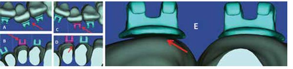
- The tray’s material and its dual-rail track tubular splines provide the “right” flexure stiffness to the appliance, which minimizes distortion and micro-movement of the tray during bonding.
- Each bracket receptacle allows for three-wall support of the bracket, giving a snug fit to the bracket and, therefore, minimizing any chance of bracket movement.
- The tray covers a substantial part of the tooth, providing reliable docking and stability of the device. This feature also allows for accurate and precise bracket transfer.
- It is reasonably easy to dock the bracket into its individual receptacle since the tray has mesial and distal channels to guide the bracket into its resting position.
- The tray can be designed modularly to accommodate for the severity of the malocclusion and avoid conflicts. This allows for the optimal, obstruction-free “fit” of the sectioned trays.
- The tray is not bulky and therefore is well tolerated by the patient and easily guided into the oral cavity.
- The tray material is translucent; therefore, the curing light can be transmitted through the body of the tray. This allows for a substantial part of the bracket to be exposed to the light.
- There are enough cutaways around the bracket receptacle to allow for the UV light to be guided around the gingival margins of the bracket in order to achieve a high cure.
- The abilities to disengage the splines after bonding and also apply leverage against the lugs on the bracket receptacle facilitate the peeling of the tray, which ultimately minimizes the potential of bracket delamination.
- Each receptacle is marked by the appropriate tooth number and can be easily cut out as a single jig to rebond the bracket if the bracket were to fail in the future. In case a replacement tray is needed, a “digital fingerprint” of the tray is accessible in the patient record, which can be used to print a replacement tray.
- The tray material is biocompatible, durable, and has a long shelf life.
- The results of preliminary studies on the accuracy of bracket transfer as a result of the suresmile IDB tray are encouraging and suggest the following: The bracket transfer is accurate to within 1 degree for angular and 0.2 of a millimeter of the planned bracket location on the virtual dental working model (Figure 35).
Discussion and conclusions
suresmile’s simulation-guided indirect bonding and IDB tools enable the ortho-dontist to more accurately and precisely bond brackets while considering the biological, functional, and esthetic needs of the patient. The suresmile digital technology and its output — the IDB tray — are only useful tools when driven by a fully developed, realistic design and plan — the inputs to the virtual target setup. A pathological virtual target setup, which is based on incorrect inputs and overreliance of the automation tools, will result in error-prone bracket locations, diminishing the value of the technology and patient care. An incorrect virtual target setup results in merely a dispensing tray for brackets; these brackets may be efficiently, yet ineffectively, bonded on a patient, reflecting a cafeteria approach to care.
We belong to an era of celebrity- and media-driven orthodontics, an era that sponsors the claim of breakthrough technologies that accelerate orthodontic care, operate autonomously, and promote a culture of “effortless orthodontics.” Currently, no such “smart technology” exists; therefore, cognitive effort must be applied by the orthodontist in order to appropriately use technology. The orthodontist must incessantly cultivate, cherish, and celebrate the cognitive and professional skills necessary to use technology effectively. Technology, in and of itself, offers limited benefits to the patient and the practice. Technology, processes, and skills must work in concert to ensure effective treatment. As such, it behooves the orthodontist to separate the wheat — the practice of professionalism — from the chaff — market-driven orthodontics.
Acknowledgment
Dr. Sachdeva sincerely thanks Nikita Sachdeva for her editorial assistance and Dr. Ed Lin for sharing the clinical images of the in vivo IDB technique.
 Rohit C.L. Sachdeva, BDS, M Dent Sc, is a consultant/coach with Rohit Sachdeva Orthodontic Coaching and Consulting, which helps doctors increase their clinical performance and assess technology for clinical use. He also works with the dental industry in product design and development. He is the co-founder of the Institute of Orthodontic Care Improvement. Dr. Sachdeva is the co-founder and former Chief Clinical Officer at OraMetrix, Inc. He received his dental degree from the University of Nairobi, Kenya, in 1978. He earned his Certificate in Orthodontics and Masters in Dental Science at the University of Connecticut in 1983. Dr. Sachdeva is a Diplomate of the American Board of Orthodontics and is an active member of the American Association of Orthodontics. In the past, he has held faculty positions at the University of Connecticut, Manitoba, and the Baylor College of Dentistry, Texas A&M. Dr. Sachdeva has over 90 patents, is the recipient of the Japanese Society for Promotion of Science Award, and has over 160 papers and abstracts to his credit. Visit Dr. Sachdeva’s blog on https://drsachdeva-conference.blogspot.com. Please contact improveortho@gmail.com to access information.
- Kalange JT. Indirect bonding: A comprehensive review of the advantages. World J Orthod. 2004; 5(4):301-307.
- Sachdeva R. BioDigital Orthodontics: Diagnopeutics with suresmile technology (Part 3) Orthodontic Practice US. 2013; 4(3):22-30.
- Sachdeva R. BioDigital Orthodontics: Outcome evaluation with Suresmile technology: part 4. Orthodontic Practice US. 2013; 4(4):28-33
- Sachdeva R. BioDigital orthodontics: Planning care with Suresmile technology: part 1. Orthodontic Practice US. 2013; 4(1):18-23.
- Sachdeva R. BioDigital orthodontics: Designing customized therapeutics and managing patient treatment with Suresmile technology: part 2. Orthodontic Practice US. 2013; 4(2):18-26.
- Akyalcin S, Cozad BE, English JD, Colville CD, Laman S. Diagnostic accuracy of impression-free digital models. Am J Orthod Dentofacial Orthop. 2013; 144(6):916-922.
- Andrews LF: Straight-wire — The Concept and Appliance. San Diego, CA: L.A. Wells Co., 1989.
- Miles PG. Indirect bonding with a flowable light-cured adhesive. J Clin Orthod. 2002; 36(11):646-647.
- Sondhi A. Efficient and effective indirect bonding. Am J Orthod Dentofacial Orthop. 1999; 115(4):352-359.
- Kalange JT. Ideal appliance placement with APC brackets and indirect bonding. J Clin Orthod. 1999;33(9):516-526.
- Gange P. Paul Gange on the present state of bonding. Interview by Homer W. Phillips. J Clin Orthod. 1995;29(7):429-436.
- Specialty Appliances. Indirect Bonding: Reference manual. https://www.specialtyappliances.com/files/pdfs/indirect_bonding_reference_manual.pdf. Accessed February 10, 2016.
- Miethke RR, Melsen B. Effect of variation in tooth morphology and bracket position on first and third order correction with preadjusted appliances. Am J Orthod Dentofacial Orthop. 1999;116(3):329–335.
- Dellinger EL. A scientific assessment of the straight-wire appliance. Am JOrthod. 1978;73(3):290–299.
- Miethke RR. Third order tooth movements with straight wire appliances. Influence of vestibular tooth crown morphology in the vertical plane. J Orofac Orthop. 1997;58(4):186–197.
- Streva AM, Cotrim-Ferreira FA, Garib DG, Carvalho PE. Are torque values of preadjusted brackets precise? J Appl Oral Sci. 2011;19(4): 313–317.
- Morrow JB. The angular variability of the facial surfaces of the human dentition: an evaluation of the morphological assumptions implicit in the various “straight-wire techniques” [master’s thesis]. St. Louis: St. Louis University; 1978.
- Meling TR, Ødegaard J. On the variability of cross-sectional dimensions and torsional properties of rectangular nickel-titanium arch wires. Am J Orthod Dentofacial Orthop. 1998;113(5):546–557.
- Cash AC, Good SA, Curtis RV, McDonald F. An evaluation of slot size in orthodontic brackets — are standards as expected? Angle Orthod. 2004;74(4):450-453.
- Grünheid T, Patel N, De Felippe NL, Wey A, Gaillard PR, Larson BE. Accuracy, reproducibility, and time efficiency of dental measurements using different technologies. Am J Orthod Dentofacial Orthop. 2014;145(2):157-164.
- Jost-Brinkmann PG, Schiffer A , Miethke RR. The effect of adhesive-layer thickness on bond strength. J Clin Orthod. 1992;26(11):718–720.
- Pitts T. Begin with the end in mind: bracket placement and early elastics protocols for smile arc protection. Clin Impressions. 2009;17(1):1-11.
- Sarver DM. The importance of incisor positioning in the esthetic smile: the smile arc. Am J Orthod Dentofacial Orthop. 2001;120(2):98-111.
- Casko JS, Vaden JL, Kokich VG, Damone J, James RD, Cangialosi TJ, Riolo ML, Owens SE Jr, Bills ED. Objective grading system for dental casts and panoramic radiographs. American Board of Orthodontics. Am J Orthod Dentofacial Orthop. 1998;114(5):589-599.
- Roth RH. Functional occlusion for the orthodontist. J Clin Orthod. 1981;15(1):32-40,44-51.
- Roth RH. Functional occlusion for the orthodontist, Part III. J Clin Orthod. 1981;15(3):174-179, 182-198.
- Stratasys. Objet 30 Pro [Machine Spec Sheet]. https://usglobalimages.stratasys.com/Main/Files/Machine_Spec_Sheets/PSS_PJ_Objet30Pro.pdf?v=635784310434644901. Accessed February 10, 2016.
Stay Relevant With Orthodontic Practice US
Join our email list for CE courses and webinars, articles and mores
