Dr. Jack Fisher discusses 10 reasons to use 3D imaging
 The specialty of orthodontics has of recent years had an influx of technology within the industry. Intraoral scanners are now being used in many practices and residency programs. We are told that this technology will eliminate alginate impressions. We are told that 3D printers will replace plaster models and perhaps print out our brackets. We are told that aligners are now returned to the practice faster with this technology.
[userloggedin]
l am still not sure how this new technology really benefits the care of our patients within the specialty of orthodontics.
The advent of 3D imaging technology has also recently come to the forefront within the orthodontic specialty. Many have stated that this type of imaging does not significantly benefit patients or aid in the diagnoses and treatment planning of their patients. The amount of radiation from older machines certainly was a concern. The recent introduction to the market of a 3D machine by Planmeca is advertised to deliver a dose of 14 ms with an Ultra Low Dose™ setting.This is a full scan taken at a .06 voxel size. If this proves to be the true dose of radiation received by this machine, then the argument for too much radiation is now not an issue any longer.
Many have argued that as orthodontists we are not trained to read this type of data of DICOM images. We are, or should be, trained within our residency training to read cephs, PAs, and submental vertex radiographs. The 3D scan of a typical patient is comprised of approximately between 450 and 600 DICOM images that are represented in the three planes of space: sagittal, coronal, and the axial planes. These are the same three planes of space we are trained to read — just many of them on the same patient.
So let’s look at the only reasons to scan a patient seeking orthodontic treatment.
1. Many have advocated that the use of 3D imaging is certainly useful in treating patients with impacted maxillary canines.
This is certainly true. However, only 1% to 2% of the population has impacted canines. Research shows that within the population of most orthodontic practices, 5% of the practice’s patients seeking treatment have impacted canines. If this is the main reason for taking DICOM images on patients, then these images should be outsourced. The cost of purchasing a 3D machine for 5% of the office’s patients does not make financial sense. A two-dimensional pan or ceph does not adequately image the impacted teeth for not only surgical planning but also the mechanics needed to move these teeth into alignment. It has been reported that 62% of palatally impacted canines are touching the roots of laterals and centrals. This is information that 3D imaging illustrates. This could often change the mechanics needed to properly position the canines without damaging the roots of adjacent teeth. However, the 3D imaging of impacted teeth certainly is advantageous to the orthodontist or oral surgeon who will surgically expose the non-erupted teeth. This is illustrated in Figures 1A, 1B, and 1C. The clinician can readily see the benefits to the patient for using the 3D imaging technology for the treatment of impacted teeth.
2. Any patient needing orthognathic surgery should receive a scan.
The scan is certainly more diagnostic in all three planes of space than a two-dimensional cephalometric image. Many oral surgeons can now use this scan to send to medical modeling companies for the construction of the splints used during the surgery. Not to mention the three planes of spaces gives the orthodontist a better perspective of the problem list prior to treatment planning and pre-surgery orthodontics. The models that are either acquired by a scan or with plaster models are incorporated in the patient’s 3D scan. The medical modeling companies can then do the surgery digitally and use the 3D models to make the surgical splints. These DICOM images give the orthodontist a more accurate visual treatment objective prior to treatment as also the digital surgery gives the oral surgeon a thorough perspective of pre-surgical planning. The patient illustrated in Figure 2 shows different types of images that can be generated from a set of DICOM images. With an exposure of only 14 microsieverts, the orthodontist can attain a pan, a ceph, and many different types of 3D images from the three simple planes of space to 3D images. Final records were acquired with an additional scan totally another 14 microsieverts.

 3. Any patients needing their anterior teeth moved in the sagittal plane.
A traditional cephalometric image is a composite of the cephalic. The true amount of bone either anterior or posterior to the roots of these teeth is not visualized in the traditional cephalometric or panoramic images. When there is not adequate bone to move the roots of teeth into a space, the clinician has only two options: Either have bone placed by a periodontist or maintain the patient’s inclination of these incisors. The use of Class II correctors has grown tremendously in the past few years. These devices often flare the lower incisors as much as 10 degrees. Fenestrations and the lack of bone support results. Is this a stable environment for incisors? We also often recline the upper incisors. Is the alveolus wide enough in the sagittal plane to accommodate the roots of the teeth? Now with the use of skeletal anchorage devices, we are more likely to exceed the patient’s biological limit. Again, a traditional ceph or pan does not show the true anatomy in this plane. The axial plane is also available with a 3D scan. This plan also gives the clinician a more thorough understanding of the availability of bone to move the incisors. Figure 3A illustrates a patient seeking treatment for a severe overjet and overbite. The pan and ceph do not reveal the enough information to properly diagnose this case. After imaging in the sagital view with a CBCT, the clinician can readily see there is a lack of bone to move the upper incisor. The patient in Figure 3B illustrates a patient with a lack of bone around the lower incisors. Again, the traditional pan and ceph do not give enough information to properly diagnose and treat this patient.
4. Any patient who will have a temporary skeletal anchorage device (TSAD) placed.
Most clinicians that have become proficient and confident with the placement and use of TSADs place them on approximately 23% of the case treatments planned in their practices. When evaluating the placement site in all three planes of space, the clinician can become very exact with locating structures that should be avoided. More TSADs are being placed in the infrazygomatic area. A 3D image is the best way to locate the best area of placement for stability in this area. See Figure 4A1 and note the thickness of the bone in the infrazygomatic crest. Compare the thickness of the bone in Figure 4A2. The bone in this figure demonstrates bone that is too thin for placement of the TSADs. More TSADs are being placed in to palatal approach. TSADs placed in the premaxilla are an area of placement that is vitally important to visualize the anatomy in this area. The clinician should consider the thickness of bone in this area to avoid the tips of the TSADs from penetrating the nasal cavity and to avoid the roots of the teeth in this area. See Figures 4B1, 4B2, and 4B3. When skillfully placed in adequate bone, the use of TSADs certainly allows orthodontists to treat their patients more consistently and predictably. The use of 3D imaging aids the clinician in the placement and use of the TSADs.


5. Any case that needs expansion of the maxilla.
Three-dimensional imaging in these cases allows the orthodontist to determine if a crossbite is skeletal or dental. The clinician can readily determine if the molars are inclined in a crossbite, or if the entire maxilla is constricted. This, in turn, then can determine what forces are desirable to correct the crossbite. The 3D images also allow the clinician to evaluate the amount of bone around the roots of the teeth that are to be expanded. This also can aid the orthodontist in the type of forces to be utilized. Maybe bone augmentation is indicated in certain areas, so the roots are not once again fenestrated through the cortical bone creating a less stable environment (see Figure 5). Figure 5A1 illustrates a maxilla that is constricted due to a narrow maxilla. Figure 5A2 illustrates the maxilla after expansion. Figure 5B1 illustrates a molar being tipped lingually. Thus a unilateral crossbite appliance was utilized.
6. Any case that possibly will be receiving a permanent implant.
The clinician placing the implants will need to evaluate the bone to determine how much area is needed between the teeth and to evaluate the thickness of the bone receiving the implant. Permanent implants are also employed to be used as anchorage during orthodontic treatment. The evaluation of the bone in all three planes of space is important for the placement and stability of permanent implants. Figures 6A and 6B illustrate an example of implant placement.
7. Any patient suspected of having a compromised airway.
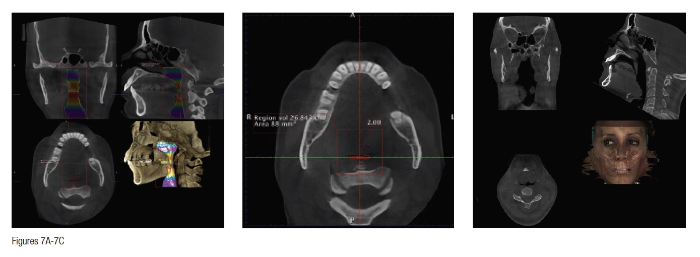
Granted, this is not known until the patient is scanned. However, if there is an inadequate airway, the location of the constriction could determine the type of treatment the patient receives. For example, it could change the treatment plan from a camouflaged treatment to a mandibular advancement. A traditional ceph is not adequate in determining the size of an airway. The subject of imaging and treating compromised airway patients is experiencing more advancements in dentistry than any other subject. It is this clinician’s opinion that the orthodontic specialist should be the most qualified clinician to aid in the treatment of these types of patients. These patients deserve a multidisciplinary approach, perhaps more than any other type patient we see in our practices. DICOM images are vitally important for the proper diagnosis and treatment of these individuals. Figures 7A and 7B illustrate this.
This patient had a chief complaint of overjet. She could be treated with the retraction of the upper anteriors. After further imaging, it was decided that a mandibular advancement would best serve her. Also, note the osteophyte on C1 that is constricting the airway. This is not a common occurrence. This osteophyte needs to be removed. So the DICOM images changed our treatment plan. Figure 7C illustrates another patient seeking treatment after surgical relapse. This patient will need to be treated with surgery again. Note the restricted airway at the hypopharynx. This must be treated prior to the retreatment of this case. Also, note the upper centrals have been torqued through the lingual cortical bone. These two problems are not viewed with conventional 2D images.
 8. Any patient with a temporo-mandibular joint (TMJ) disorder.
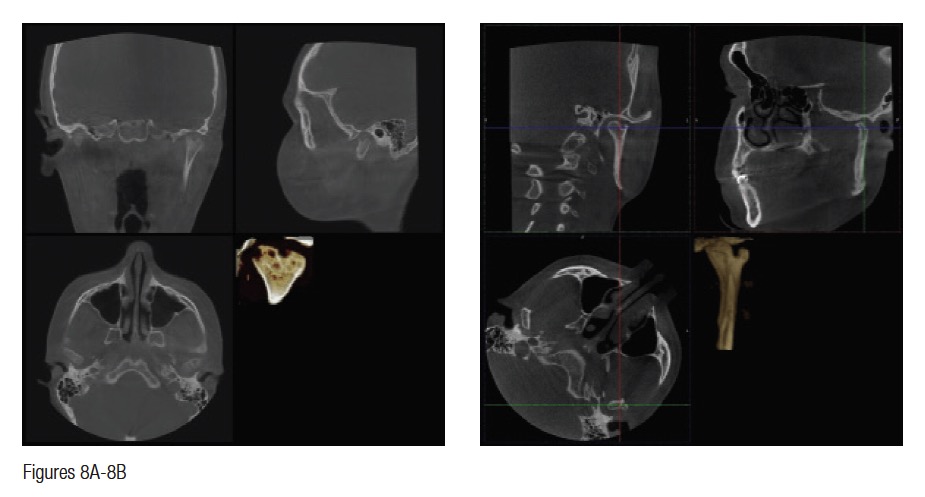
Once again, this is not always known prior to the scan. Internal joint disorders are often found during the manipulation of the DICOM images. For example, the etiology of an open bite in a female teenager may be due to idiopathic condylar resorption. Is it not best to know this on the front end of orthodontic treatment? Many joint conditions are asymptomatic for patients seeking routine orthodontic treatment. Most joint problems are not visualized on the routine pan and cephs. Being able to image the TMJ in all three planes of space is imperative in patients receiving comprehensive orthodontic treatment. Figure 8A illustrates a 14-year-old female with obvious challenges of her condyles. She happened to be asymptomatic. However, it is better to have the information before orthodontic treatment so the patient and the parent are fully informed of this condition. Figure 8B illustrates a bifid condyle that is also asymptomatic. Neither of these two conditions was visualized on the traditional pan and ceph.

9. Any patient having super-numerary teeth that are not imaged in a routine pan.
Once again, this is not known until the scan is taken and read by the clinician. I personally have found supernumerary teeth that were not in the trough of the routine pan. We have found mesiodens that were not visualized on the pan. Figures 9A and 9B illustrate a patient for whom the mesiodens was not obvious on the pan or the ceph. However, the extra tooth is imaged on the sagittal view of the scan (Figure 9C). The etiology of the reclined centrals is the mesiodens. If the scan had not been taken, this may have been missed.

10. Any patient having pathology that is not imaged on the routine 2D radiographs traditionally taken on the orthodontic patient.
Again, we are not aware of these conditions that may exist prior to making a decision of what kind of images we need on a patient presenting for orthodontic treatment. Figure 10 illustrates just a few of the conditions that were discovered on the 3D images but were not evident on the traditional 2D images. The first patient in Figure 10A shows a patient in the axial view where C1 is rotated to the patient’s left. This is also restricting the airway. Figure 10B illustrates a patient who was scheduled for a maxillary osteotomy. The maxillary left sinus is not present. This is reported to be a condition that is present in 1:100,000 people. I believe this condition to be more frequent, having seen this condition in three patients in the last 3 years. Figure 10C illustrates in all three planes of space an enlarged pituitary gland. This patient’s pituitary gland had to be removed. Figure 10D shows a patient with a large traumatic bone cyst. This was not readily evident on the pan because the lesion is so large. This was biopsied and was determined to be a traumatic bone cyst. Figure 10E illustrates a large nasal bone cyst. We have discovered several smaller ones over the past 3 years that were not evident on a pan. This one, however, was evident on the pan. The enlarged pineal gland was not demonstrated on the pan or ceph but is evident on this image in the sagittal plane of space. Figure 10F1 illustrates a osteophyte on C1 of a 26-year-old female. Figure 10F2 shows a different view. This patient was referred for a sleep study and was diagnosed with severe sleep apnea. The osteophyte has been removed. We have illustrated only a few of the conditions we have discovered.
The routine use of DICOM imaging in the specialty of orthodontics may be approaching. We actually just used the term “routine.” This raises a question. We as a specialty do not get to determine what is a standard of care. This is determined by the courts. Any of the 10 reasons discussed in this article that were not imaged thoroughly and perceived as less than adequate treatment delivered could be brought into question in a judicial environment. Yes, we are liable for all the data obtained with a scan. We are also liable for the data we do not care to image when more and more clinicians are using routine DICOM images. How and why did pans and cephs become routinely utilized in the specialty? We are specialists. We should educate ourselves accordingly and use the technology available to treat the patients who trust us with their care. If it is in fact a truth that the newer machines are delivering the dosages of radiation as advertised, there is no longer an excuse to not learn and educate ourselves to better treat our patients.
Reprinted with permission of Dentaltown Magazine and Dentaltown.com
[/userloggedin]
[userloggedout][/userloggedout]
Stay Relevant With Orthodontic Practice US
Join our email list for CE courses and webinars, articles and mores
