CEU (Continuing Education Unit): 2 Credits
Educational aims and objectives
This article aims to discuss “inverting” incisor brackets (placing them upside-down) to reverse the prescription torque from positive to negative.
Expected outcomes
Orthodontic Practice US subscribers can answer the CE questions by taking the quiz to earn 2 hours of CE from reading this article. Correctly answering the questions will demonstrate the reader can:
- Identify the traditional orthodontic approach when significant crowding or protrusion exists.
- Realize methods other than creating arch length via extractions when significant crowding or protrusion exists.
- Identify the method of “inverting” incisor brackets (placing them upside-down) to reverse the prescription torque from positive to negative.
- Realize that because of prescription
- Observe the setups referred to as “Inverted A” and “Inverted B.”

Dr. Chad Foster illustrates a technique for patients with moderate-to-severe crowding or protrusion
Establishing proper labiolingual inclination of the upper anterior teeth is considered a high esthetic priority in orthodontic treatment. Significant crowding and protrusion of the upper anterior teeth are two of the more common motivating factors for patients seeking orthodontic treatment.1 The final antero-posterior (A-P) position and inclination of the maxillary anterior teeth play a major role not only in smile esthetics, but also in facial profile and the position of the lips.2 Achieving proper labiolingual inclination has even been shown to be more important esthetically than the A-P position of the anterior teeth.3 Treatment planning with this end in mind, particularly in cases with significant pretreatment crowding or protrusion, can be quite a challenge.
The traditional orthodontic approach when significant crowding or protrusion exists involves creating space within the dental arch, which can then be consolidated to allow alignment of crowding or retraction of the proclined anterior teeth. Often this creation of space is achieved through a bicuspid extraction pattern.
Other than creating arch length via extractions, there are various other methods at the orthodontist’s disposal in these types of cases. These include manually adjusting torque in the archwire, variable torque brackets, interproximal reduction, expansion of the dental arch, auxiliary torqueing springs, and others.
Another technique that has been popular for some time is “inverting” incisor brackets (placing them upside-down) to reverse the prescription torque from positive to negative. Dr. Earl Johnson recommended this as a technique to exert labial root torque when upper lateral incisors are blocked out to the lingual.4 Dr. Tom Pitts has coined the term “flipping” to refer to this technique when it is applied to the upper incisors as a group and has advocated its clinical use for many years.5
The protocol to be described in this article is submitted as a means to maximize the efficacy of inverting upper incisor brackets in cases exhibiting moderate-to-severe crowding or protrusion. This approach is most beneficial in cases where the orthodontist is on the fence between an extraction or non-extraction treatment approach, commonly referred to as “borderline cases.”
An important note — while many of the concepts to follow are universal in application, the protocol discussed is specific to a traditional 0.022 rectangular slot appliance.
“Inverted A” versus “Inverted B” — understanding prescription consequences and compensations
When inverting U2-2, an understanding of the prescription of these brackets is important. The straight-wire appliance, developed by Dr. Larry Andrews, relies on brackets designed to achieve precise, three-dimensional control of crown and root position.6 The prescription is specific and requires that each bracket is applied to the correct tooth in normal orientation. Brackets are not designed to perform with the same degree of accuracy or control when they are inverted. Inverting brackets often comes with clinical consequences that require some type of compensation by the orthodontist in order to achieve the intended tooth position.
Regarding tooth alignment, it is considered ideal for the upper central incisor crown to have slightly greater positive labiolingual inclination relative to the upper lateral incisor; hence, the greater positive torque prescription for U1 brackets versus U2 brackets. However, in an inverted setup where the upper incisor brackets are inverted on their correct teeth (U1s on U1s and U2s on U2s), the upper central incisors will now have a slightly stronger effective negative torque applied to them relative to the upper lateral incisors. I will refer to this, the most common inverted setup, as “Inverted A.”
In my experience, this unfavorable relative torque discrepancy can become visually evident in larger dimensional wires. It might be hard to believe that this slight difference in torque would express itself, but the reason it does has to do with the archwire “engaging the low couple” of the inverted bracket (discussed in the next section), which effectively removes “slop” and works toward complete expression of prescription torque. The orthodontist’s compensation in an “Inverted A” setup is to either place very slight additional positive torque to the U1s or very slight additional negative torque to the U2s via third order adjustments to dimensional archwires. These adjustments can be in the form of wire bending or “bleeding torque” by very slightly reducing the corners of the rectangular wire in the area of the upper centrals with a handpiece.
My preference when inverting U2-2 brackets is to place lateral incisor brackets on all four of the upper incisors. I will refer to this setup as “Inverted B.” I find this effective for two main reasons. First, while negative torque is the goal, the negative torque provided by the inverted U2 bracket is less likely to be excessive compared to the inverted U1 bracket. Expression of excessive negative torque is typically the most unfavorable risk of using an inverted setup. The fact that it is the lesser of the two negative torques also allows the setup to have a bit more range to advance into larger dimensional wires (18 X 25 and above,) which permits greater third order control of the U3-7 brackets, which are in normal orientation.
An “Inverted B” setup still has a prescription consequence that requires compensation. While this setup has less of a third order (torque) consequence compared to an “Inverted A,” there is instead a first order error introduced that now needs to be compensated for. An U2 bracket has a greater labiolingual offset built into the base of the bracket to allow the facial surface of the lateral to be very slightly lingually positioned relative to the central for ideal tooth position. The compensation here is small first order bends to the archwire between the U1 and U2 to step the U1 slightly out toward the facial (an amount equal to the base depth difference between an U1 and U2 bracket).
I personally find this compensation much easier than the torque compensation required in an “Inverted A” setup, and this is the second reason that I prefer “Inverted B.” Additionally, this very slight first order archwire bend has a beneficial collateral effect on the relative torque between U1 and U2. As with any first order bend, there will be a minimal collateral effect on torque. In this case, even though the inverted U2 brackets on all four upper incisors are delivering the same negative torque, the addition of the first order bend between U1s and U2s will result in slightly less negative torque applied to the U1s, which is closer to the ideal relative labiolingual inclination difference between these teeth.
It is also important to note that there is a slight second order (tip) difference between an U1 bracket and an U2 bracket. This however is easily seen and compensated for in bracket placement when visualizing the slot of the bracket relative to the long axis of the tooth.
Understanding “low couple” activation in an inverted U2-2 bracket setup
The following may harken back to physics class, but a refresher is helpful! A simple couple is a pair of equal and opposite forces whose lines of action do not coincide. These forces have a turning effect (moment) called torque, about an axis which is perpendicular to the plane of the forces. Simply put, torque is the turning effect that occurs when the corners (diagonal dimension) of the archwire engage a couple in the walls (also known as a lock point) of the bracket slot. When rotating the archwire within the bracket slot, larger dimensional wires will engage a high couple on one lock-point end range and a low couple on the other lock-point end range (Figure 1).
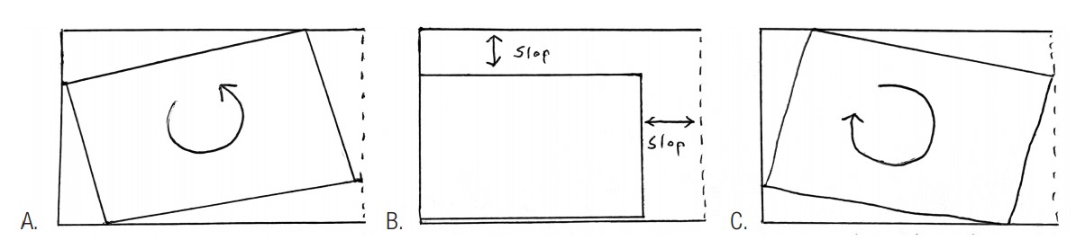
When the corners of the archwire are engaging the couple, there is very little “slop,” and the prescription in the bracket will theoretically be expressed very accurately. You can test this out with a larger dimensional wire in the slot of an incisor bracket. At the top end or low end of where you can rotate the wire to simulate torque (Figures 1A and 1C), there is almost no “slop” or play in the wire in rotation (first order) or tip (second order). But in between these high and low couple lock points, the corners of the wire do not fill up the slot, and there is excess first order and second order “slop” (Figure 1B).
Understanding the following concept is key to understanding the activation at work in an inverted incisor setup. When a large enough dimensional archwire is inserted into inverted brackets on upper incisors that are excessively proclined (either because they started in this position or because alignment of significant crowding takes them to this position), the corners of the wire will engage the slot at the low couple lock point. This occurs when the degree of labiolingual inclination of the crown of the tooth is greater than the degree specifically limited by the low couple lock point (Table 1). In this scenario, the torquing moment is now active and will be expressed in tooth movement. Theoretically, the excessive labiolingual inclination of the tooth will be reduced until the degree limited by the low couple lock point is reached. In other words, the proclined tooth will rotate until it reaches the position allowed by the low couple at which point the torqueing moment is no longer active.
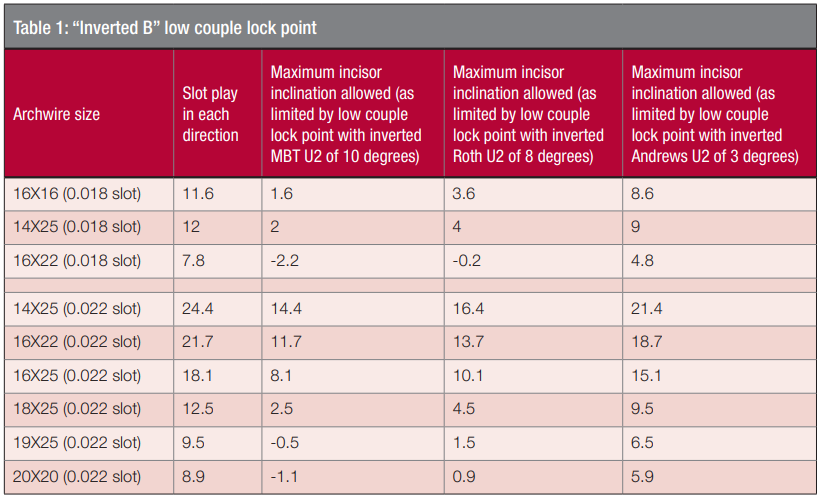
In an inverted setup, the goal is to have the torqueing moment cease when the inclination of the tooth has been reduced to the desired position. Thus, targeting an endpoint that leaves the incisors in an ideal esthetic position should be the goal. This has everything to do with selecting the right dimensional archwire. For perspective, Andrews states that the ideal crown inclination of an upper central incisor is 7 degrees.6 Another study found that an inclination of less than 5 degrees is relatively more preferable.2
Table 1 is a helpful guide to estimate the resulting labiolingual inclination of the incisors after an “Inverted B” setup has completed its activation. This theoretical endpoint obviously varies depending on bracket torque and archwire size. My reference for slot play in Table 1 is Earl Johnson’s article,4 which takes into consideration that wires are typically undersized, and slots are typically oversized. However, true slot sizes and wire sizes can vary greatly so these numbers should be used only as a theoretical guide.
Additionally, throughout expression of the torqueing moment and also at its endpoint, there will be almost zero “slop” in the system in regards to rotation or tip. This means that any consequences in the altered (inverted) straight-wire prescription will also be equally well expressed. As previously discussed, in an “Inverted A” setup, the unfavorable relative torque differences between U1s and U2s will probably be observed within a few months. In an “Inverted B” setup, the unfavorable in/out relative position of U1s to U2s within will most likely be seen in a few months. Even slight archwire adjustments made to the upper incisors in this setup are likely to be well expressed in tooth position.
Archwire progression
It is important for archwire progression in an inverted U2-2 setup to be strategic. Obviously, round wires will not engage a couple in either normal or flipped orientation. In cases with normal orientation, I most often use a three-wire sequence of 14N, 20N X 20N, and a third and final wire that may be anywhere from 16N X 25N to 19N X 25N in dimension and of either stainless steel or TMA. The 20N X 20N wire is used throughout the pano/repo appointment in normal orientation setup. In an inverted U2-2 setup, however, I will opt to use a 16N X 22N as the second (middle) wire in the upper arch instead of the 20N X 20N. I use the 16N X 22N wire here because in the flipped setup (assuming some degree of proclined incisors), it is large enough to allow the low couple lock point to provide acceptable first order and second order control for pano/repo purposes. Additionally, the 16N X 22N is small enough in dimension to not significantly engage the low couple. Generally speaking, I prefer to not significantly engage the low couple to produce the desired negative torque until after the pano/repo appointment is complete, and the patient is in more full size dimensional stainless steel wires. The reason for this is explained in the next section. If a different dimensional wire such as 20N X 20N or 16N X 25N were used as a middle wire in the inverted setup, the low couple would be more actively engaged.
Finishing wires and interproximal reduction (IPR)
Reducing upper incisor proclination to establish ideal labiolingual inclination is typically the goal in an inverted U2-2 setup. In larger dimensional wires when the low couple is engaged, the moment created will begin to produce a combination of labial (positive) root torque and lingual (negative) crown torque. In an effort to tip the scales toward greater lingual crown torque, my preference is to not significantly engage the low couple until I have performed IPR in the upper arch. The interproximal space created prevents proximal contact binding between the anterior teeth as the torqueing moment is created, which allows a greater expression of the lingual crown torque component. In the absence of this space, the binding of the incisors at their contact points, below the incisors’ center of resistance, will allow a relatively greater degree of labial root torque. This is often less favorable depending on the amount of bone labial to the roots of the incisors within the alveolus.
In anticipation of significant IPR (regardless of normal or inverted setup), it is important that the pano/repo is completed first. This is important for two reasons that have to do with posttreatment relapse. First, it is important that first order rotation issues are normalized so that the new interproximal contacts are as close to 90 degree abutments as possible. IPR done prior to this, when rotations still remain, are very likely to create angled contact points that are ready-made for relapse of the original rotation. I call these “relapse contacts.” Second, if root position (tip/second order) is not ideal, and IPR contacts are created in this position, there is a tendency after treatment that these roots will naturally attempt to upright to their ideal positions, which could unfavorably alter the esthetic contacts of the anterior teeth. If early IPR prior to ideal alignment and root position is necessary, it is important to consider performing it again later once these issues are idealized.
Following pano/repo, I will advance from the 16N X 22N to a 16 X 25 SS archwire and perform IPR. Depending on the case, IPR will be performed from U2-2, U3-3, or U4-4 depending on the amount of protrusion present. My preferred IPR tool is a 0.3 mm rigid coarse disc in a slow -speed handpiece. Additionally, unless there is excess overjet present, I will typically perform IPR in the lower arch at the same time. One key concept to keep in mind is that while the low couple moment is active, do not run out of overjet! While the moment is active, if the upper incisors are in contact with the lower incisors (preventing lingual crown torque), there will obviously be relatively greater labial root torque expressed.
If further retraction is needed, and if the micro-esthetic tooth form allows for additional IPR (larger barrel or triangular shaped incisors), I will perform a second IPR session. Two factors are considered in regards to how much IPR should be performed. First, I do not like to appreciably compromise micro-esthetic tooth form, so I will do less on smaller teeth. Second, I will not remove more than 50% of proximal enamel,7 which varies depending on tooth size, but typically not exceeding .75 mm at each contact point of the lower incisors (slightly more at upper incisors) as recommended by Sheridan.8
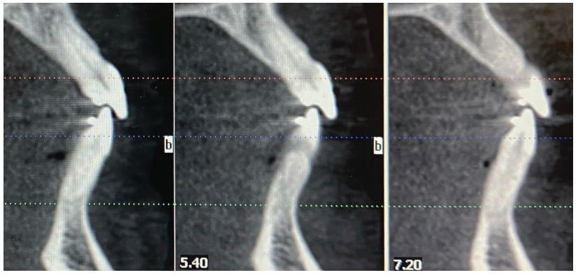
An additional tactic when further reduction of protrusion is needed is to progress to a larger archwire to create a stronger moment from greater low couple engagement. From a 16 x 25 wire this progression is most often to an 18 X 25 SS or 19 X 25 SS. If progression into a larger dimensional wire is indicated, it is important to monitor the patient closely to make sure that the roots of the upper incisors do not violate the labial aspect of the alveolar housing. This is an active appliance, and if the patient is not seen for an extended period of time while in larger dimensional wires, there is risk of overcorrection and periodontal consequences. This is why, except for select cases, I often do not progress past a 16X25 dimension archwire. The best way to monitor root position is with CBCT sectional images, but palpation of the upper anterior alveolus and cephalometric radiographs can help in this regard as well. Once the ideal labiolingual inclination is achieved, the moment producing the torque can be deactivated by reducing the size of the archwire or by “bleeding torque” off the wire by lightly reducing the corners of the wire in the U2-2 area with a high speed. In certain cases it is even necessary to reposition the inverted incisors to normal orientation if negative torque seems at all overexpressed.
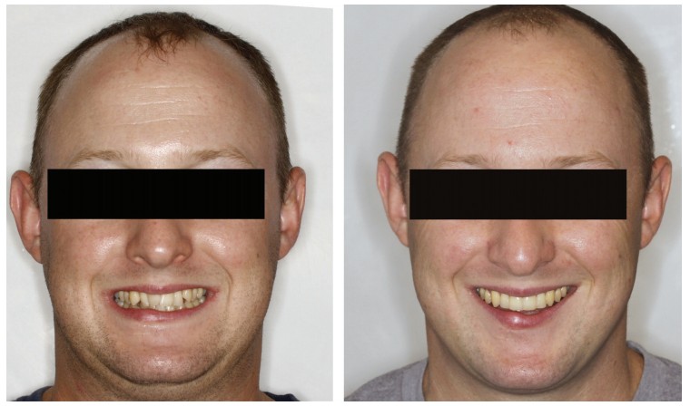
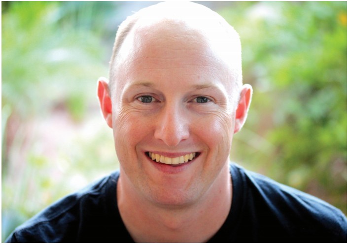
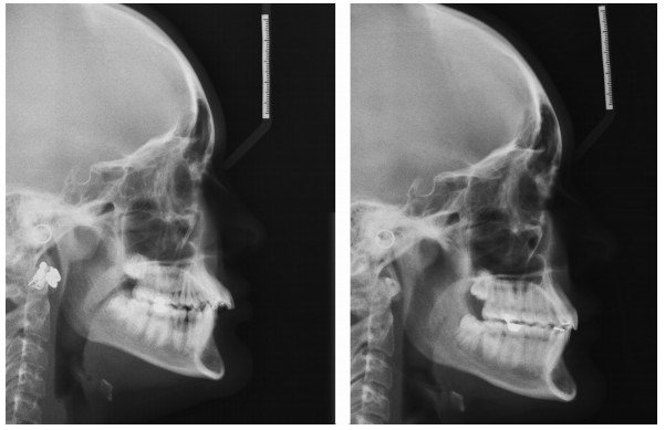
Case report No. 1
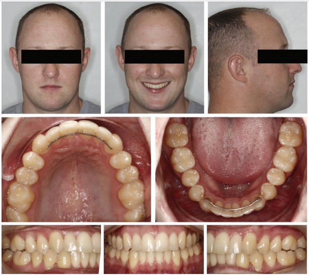
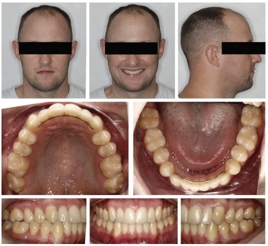
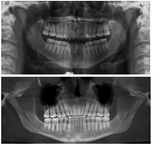
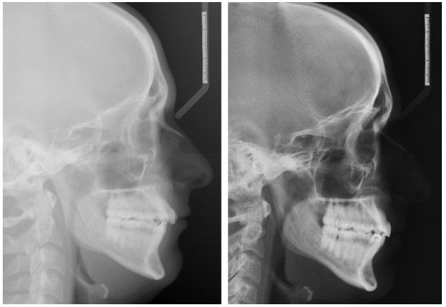
I am a proponent of orthodontic diagnosis from “Outside-In” as recommended by Dr. David Sarver.9 In regards to the macro-esthetics (facial) of this case, I was concerned with what I viewed as a deficient midface, unfavorable tight/thin lips, and a relatively flat profile. In regards to mini-esthetics (smile), I felt that the patient would benefit from increasing esthetic projection of arch width via mild arch expansion of posterior teeth. In regards to micro-esthetics (teeth), I knew that IPR would be a great benefit due to his mild triangular incisor shape and to address the appearance of dark gingival embrasures as the severe crowding aligned. I chose not to extract in the upper arch due to my macro-esthetic soft tissue concerns, which I viewed as very sensitive to over-retraction. In the lower arch, I think this case could have been well treated with a lower incisor extraction, but my plan did not include this. Instead, over the first 4 months of treatment as the crowding aligned, the patient was seen every 3-4 weeks to perform very light hand-strip IPR on the lower arch (less than 0.1 mm per contact each time). This was done in an effort to reduce proximal binding of the lower anteriors as the alignment of their severe crowding unraveled. His U6s had prominent lingual cusps that, even when reduced, prevented full non-working (buccal) cusp seating (evident pre- and posttreatment).
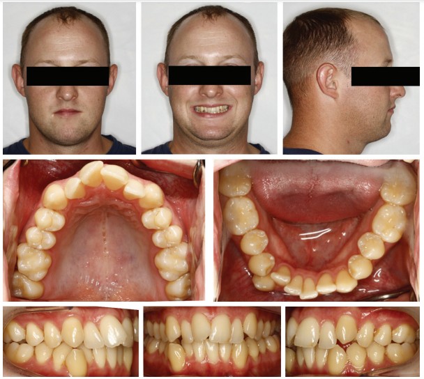
The case was treated in 22 months. “Inverted B” setup with 0.022 MBT Alpine brackets (Rocky Mountain Orthodontics) was used and approximately 0.75 mm IPR was performed at each contact U3-3 and L4-4. Mild arch expansion was achieved through use of Norris extra broad NiTi archwires (DynaFlex®) in sizes 14N and then 16N X 22N. Then, 16 X 25 SS archwires were used in finishing.
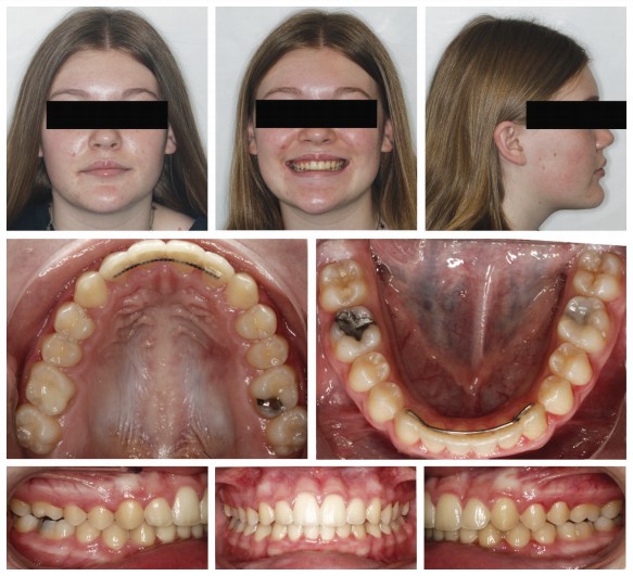
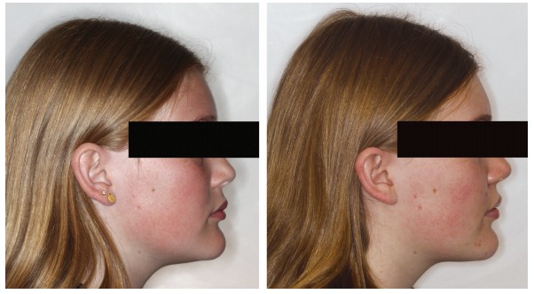
Case report No. 2
In my opinion, the macro-esthetics (facial) presented a bit of a conundrum. Obviously, correction of the protrusive upper incisors to establish ideal labiolingual axial inclination was of primary importance in this case (to patient and parents as well). However, I very much liked the presentation of her lips, and did not wish for their retraction. Also, the strong chin prominence esthetically requested that the lips remain close to where they were so as not to further relatively highlight this prominence. In regards to the vertical of the lower facial one-third, I felt that decreasing would further project the chin via autorotation of the mandible. My decision was to treat without extractions which I viewed as having greater potential for over-retraction of uppers and also slight risk of vertical decrease.
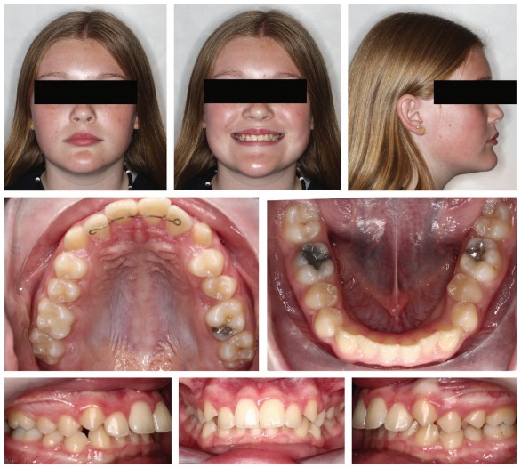
The case was treated in 22 months. “Inverted B” setup with 0.022 MBT Alpine brackets (Rocky Mountain Orthodontics) was used along with Class II elastics and approximately 0.4 mm IPR was performed at each contact between U3-3 and L3-3. Mild arch expansion was achieved through use of Norris extra broad NiTi archwires (DynaFlex) in sizes 14N and then 16N X 22N. Then 16 X 25 SS archwires were used in finishing.


After reading this article on inverting incisor brackets, see Dr. Stuart Frost’s non-extraction treatment for face-driven treatment planning here:
https://orthopracticeus.com/non-extraction-treatment-for-face-driven-treatment-planning/
Author Info
 Chad Foster, DDS, MS, is a Board-certified orthodontist and owner of Butterfly Orthodontics in Phoenix, Arizona. A graduate of Chapman University, he earned his Doctor of Dental Surgery and a master’s degree in craniofacial biology, and completed his orthodontic residency at the University of Southern California (USC). Dr. Foster loves orthodontics and supporting his orthodontic colleagues. He is an avid reader, a prolific writer, and lectures internationally, most often on the topic of orthodontic esthetics. He serves as the Directing Editor of Orthotown magazine.
References
- Samsonyanova L, Broukal, Zdenek. A systematic review of individual motivational factors in orthodontic treatment: facial attractiveness as the main motivational factor in orthodontic treatment. Intl J Dent. 2014;2014:938274.15
- Ghaleb N, Bouserhal J, Bassil-Nassif N. Aesthetic evaluation of profile incisor inclination. Eur J Orthod. 2011;33(3):228-235.
- Cao L , Zhang K, Bai D, et al. Effect of incisor labiolingual inclination and anteroposterior position on smiling profile aesthetics, Angle Orthod. 2011;81(1):121-129.
- Johnson E. Selecting custom torque prescriptions for the straight-wire appliance. Am J Orthod Dentofacial Orthop. 2013;143(suppl 4):S161-S167.
- Pitts TR. Bracket Positioning for Smile Arc Protection. J Clin Orthod. 2017;51(3):142-156.
- Andrews LF. Straight wire: the concept and appliance.A. Wells Co.: San Diego, CA; 1989.
- Pinheiro MLR. Interproximal Enamel Reduction. World J Orthod. 2002;3(3):223-232.
- Sheridan JJ. Guidelines for contemporary air-rotor stripping. J Clin Orthod. 2007;41(6):315-320.
- Sarver, David. Dentofacial Esthetics: From Macro to Micro. Quintessence Publishing Co.: USA; 2020.
Stay Relevant With Orthodontic Practice US
Join our email list for CE courses and webinars, articles and mores
