McLaughlin Bennett 5.0 significantly changes appliance and archwire design. Read Dr. Richard McLaughlin’s article to find out the details of this updated system.
Dr. Richard McLaughlin discusses the updated system that promotes increased clinical efficiency
Introduction
Over the course of more than 40 years practicing orthodontics, I have worked with a number of orthodontic appliances, including the original Straight-Wire® Appliance (Ormco Corporation) developed by Dr. Larry Andrews. Most recently, working with Dr. John Bennett and the Forestadent Corporation in Germany, the McLaughlin Bennett 5.0 (MB 5.0) system has been developed. The system incorporates a number of significant changes based on our collective clinical and appliance design experience.

MB 5.0 is a fifth-generation design that builds on previous designs, including the original Straight-Wire Appliance. Previous designs included changes in all dimensions — tip, torque, and in/out values.
The MB 5.0 appliance system was developed in concert with Forestadent in Germany and involved adjustments to the values and design of their Mini-Sprint system that we had worked with for 18 months. The tip, torque, and in/out dimensions were a combination of ideas from our third- and fourth-generation appliances. The changes were built on our collective clinical experience as well as changes in archwire materials, dimensions, and shapes, as well as changes to our mechanics to increase clinical efficiency. In addition, other significant features were added, including an integral base that enhanced reliability and esthetics. This article will detail how we arrived at the values incorporated in MB 5.0.
Background
The Straight-Wire Appliance
After graduating from the orthodontic program at USC, I began working for Dr. Lawrence Andrews in San Diego. He had finished collecting his 120 non-orthodontic normal study models, taken on untreated cases, and considered to have ideal occlusions. He evaluated these models and determined there were six key features that were present in all 120 of the models, which he detailed in his classic article, “The Six Keys to Normal Occlusion.”1 He followed this by measuring the tip, torque, and in/out values of each tooth on the models, which were used to design the original Straight-Wire Appliance, which significantly reduced the need for wire bending.
During this period, I met Dr. John Bennett from London, England, and Dr. Hugo Trevisi from Sao Paulo, Brazil. We became good friends and colleagues, and they also began using the Straight-Wire Appliance with sliding mechanics.
The Mclaughlin Bennett Trevisi 3.0 appliance
In 1997, we began designing a third orthodontic appliance, the “McLaughlin, Bennett, Trevisi” appliance. The appliance had tip, torque, and in/out values that were based on two factors:
- The Andrews’ non-orthodontic normal measurements, as baseline references for tip, torque, and in/out values in the appliance
- The play between the .019 x .025 archwire, and the .022 bracket slot. This play was approximately 10°. This amount did not significantly change the in/out values and only minimally changed the tip values, but it significantly changed the torque values. For example, the non-orthodontic normal torque value for an upper central incisor was 7°. The torque value required in the new bracket for the upper central incisor was 17°. This was necessary to accommodate the 10° of play between the bracket slot and the archwire.
In addition to the development of this appliance, we began using lighter force sliding mechanics (200 grams versus the previous standard 600 grams). With lighter forces, there was enough stiffness in the .019 x .025 rectangular steel archwires to avoid deflection and, hence, the need for the additional wire bending, such as reverse curve of Spee bends.
The MB 4.0 bracket
Our fourth experience with the pre-adjusted appliance began in 2009 with the Mclaughlin Bennett MB 4.0 bracket. Two important changes were introduced into the appliance. The first included reducing the in/out values of the upper lateral incisors from approximately .5 mm of in/out to approximately .25 mm of in/out thickness. This change brought the upper laterals slightly forward into better alignment with the upper centrals and canines. The second change was with the lower canines. When the bite deepened even minimally, the lower canines with -6° of torque tended to incline even more lingually. This was followed by some extrusion of the upper canines. Placing 0° of torque in the lower canines moved them to a more upright position and provided better support for the upper canines. These changes, although minimal, proved to be beneficial in this esthetic anterior area.
The appliance was developed using a new manufacturing technique, which was more accurate than a metal injection molding process. The slot was milled at .0220 because it was unnecessary to deal with the heating, cooling, and shrinkage factors of a molding technique. However, the slot size change that had been introduced was not advantageous. Ironically, since the slot size was much more precise than previous brackets, it was too small for a .0195 x. 025 archwire. The result was too much torque in the appliance system, which was most evident in the upper incisors.
The Forestadent 5.0 bracket
The experience with the previous four pre-adjusted appliances was invaluable as we began working with the Forestadent team. We started by using their Mini-Sprint II appliance, a very comfortable transition, since many features of this appliance were comparable to our previous appliances. We treated cases with Mini-Sprint II for a period of a year and a half, from the beginning of 2017 until August of 2018. Then the 5.0 bracket system was completed and released in the fall of 2018. The tip, torque, and in/out dimensions were a combination of ideas from our third and fourth appliances. In addition, there were other features added that were significant improvements. Each bracket was a single piece design with an integral base. This eliminated the need for the brazing process and prevented any separation or discoloration between a mesh pad and a bracket.
Discussion of each of the components of MB 5.0, including clinical considerations
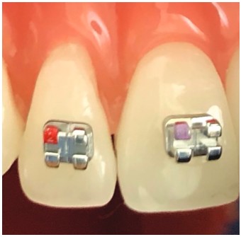
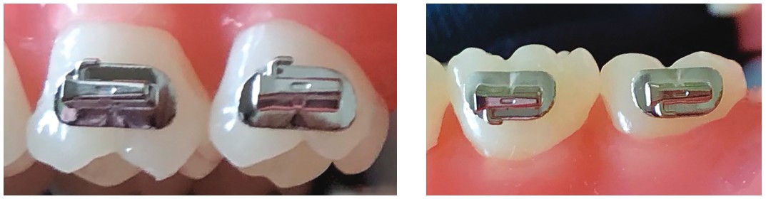
The upper central and lateral incisors (Figures 1-2)

The upper central incisor brackets have +17° torque and +4° angulation; the upper lateral incisors +10° torque and +8° angulation. The upper lateral incisors also have reduced in/out values in comparison with the Andrews norms and previous versions. This provides a better relationship with the adjacent centrals and canines. In cases with palatally displaced upper lateral incisors, it is beneficial to invert the upper lateral incisor brackets to create -10° torque instead of +10° of torque (Figure 2). This creates the necessary labial root torque to aid in moving the lateral root forward.
Lower incisors (Figure 3)
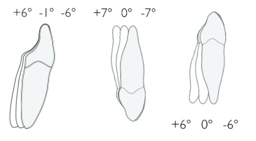
The Andrews norm for lower incisor tip is +2°. The brackets can be adjusted for minimal tip as needed at the time of placement. Torque is a challenge with lower incisors because of the thin labio-lingual bone. -1° of torque is best for Class 1 cases. And -6° of torque is best on Class II cases, especially when Class II elastics are needed. And +6° degrees of torque is best on Class III cases, especially when Class III elastics are needed.
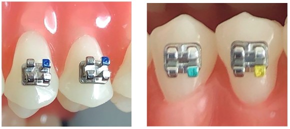
Upper canines (Figure 4)
The upper canine brackets have +8° of tip, which is adequate for canine guidance. The routine upper canine torque used is -7°; however, inverting to +7° is occasionally needed if the upper canine root is very prominent, especially when showing labial recession. Because of the shape and prominence of the canines, the in/out dimension of the canine brackets is very minimal. Both upper canines are available with hooks. Because of their strategic position in the dentition, hooks are very useful for various types of elastics (Class II, Class III, and anterior cross elastics).
Lower canines (Figure 5)
Lower canines routinely have +3° of tip and 0° torque. But when there is labial root prominence of the lower canines, the canine bracket can be inverted to -6° torque. Lower canines have hooks, as these teeth are in very strategic positions for Class III elastics.
Switching lower canines (Figure 6)
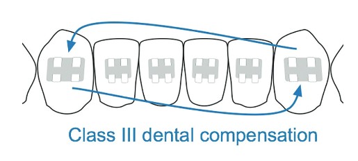
In many Class III cases, lower canines are tipped distally, as are the lower incisors. It is most important to maintain the distal crown tip on the lower canines on these cases to prevent the incisors from being pushed forward. Therefore, switching lower canines from right to left and left to right will create -3° of tip on each lower canine, as opposed to the normal +3° of tip.
Upper bicuspids (Figure 7)
The upper first and second bicuspids have -7° of torque and 0° of tip and are available with or without hooks. All four upper bicuspids are interchangeable, which is very helpful with inventory. The brackets can be placed slightly to the mesial of the center of the upper bicuspid crowns. This rotates them to the distal and brings the buccal cusps closer to a Class I position, especially when the second bicuspids are small. Bicuspids without hooks are preferred for patient comfort purposes, as the hooks are seldom used. At the end of the case, settling elastics are normally attached from the lower arch to the upper posterior bracket wings. There are usually no wires on the upper posterior teeth and no ties on the upper bicuspid and molar brackets during the settling process.
Lower first and second bicuspids (Figure 8)
Lower first and second bicuspids both have 2° of tip. The first bicuspid has 12° of torque, and the second bicuspid has 17° of torque and are available without hooks (Figure 8), or with hooks.
Conventional upper first and second molar tubes (Figure 9)
The Straight-Wire Appliance upper first and second molar tubes had 5° of tip. This was due to the brackets being oriented to the buccal groove of the clinical crowns, leaving them tipped up 5° on the mesial. Our decision on the conventional upper first and second molars was to place the brackets parallel to the occlusal plane with 0° of tip for easier visualization. Both positions achieve the same positive results. The tubes have -14° of torque and 10° of distal rotation. They have a funnel-shaped entrance for easier wire placement.
Lower first and second molar tubes (Figure 10)
The lower first molar has -20° of torque, and the lower second molar has -10° of torque. They have zero offset and zero angulation. As with the uppers, they have a funnel-shaped entrance for easier wire placement.

Upper and lower second molar mini-tubes (Figures 11-12)
The design of the upper- and lower-second molar mini-tubes allow for placement when the second molars are not fully erupted. Despite the small size, they provide good tooth control, patient comfort, and less interferences. They are placed on the middle of the mesio-buccal cusps of these teeth. The upper tubes have 0° tip, 4° of rotation, and -14° of torque. The lower mini-tubes have 0° tip, 0° of rotation, and -10° of torque.
Before developing McLaughlin Bennett 5.0, Dr. McLaughlin wrote “Orthodontics is moving forward” for Orthodontic Practice US. Read his article here. https://orthopracticeus.com/columns/orthodontics-moving-forward/
 Richard P. McLaughlin, DDS, completed his orthodontic training at the University of Southern California in 1976. Since then, he has been in full-time orthodontic practice in San Diego, California. He has lectured extensively in the United States as well as internationally. He is a member of the Pacific Coast Society of Orthodontists, the American Association of Orthodontists, and a Diplomate of the American Board of Orthodontics. He is the Past Component Director of the Southern California Component of the Edward H. Angle Society of Orthodontists and Past President of the National Angle Society. He is the recipient of the 2009 American Board of Orthodontics Dale Wade Award as well as the 2010 Pacific Coast Society of Orthodontists Award of Merit. In addition, Dr. McLaughlin is a clinical professor at the University of Southern California, Department of Orthodontics in Los Angeles, California, and an associate professor at Saint Louis University, Department of Orthodontics. He has written more than 30 journal articles and co-authored five textbooks.
Disclosure: Dr. McLaughlin is a key opinion leader for Forestadent.
- “The Six Keys to Normal Occlusion.” Andrew, LF. Am J Orthod Dentofac. 1972;62(3):296-309.
Stay Relevant With Orthodontic Practice US
Join our email list for CE courses and webinars, articles and mores
